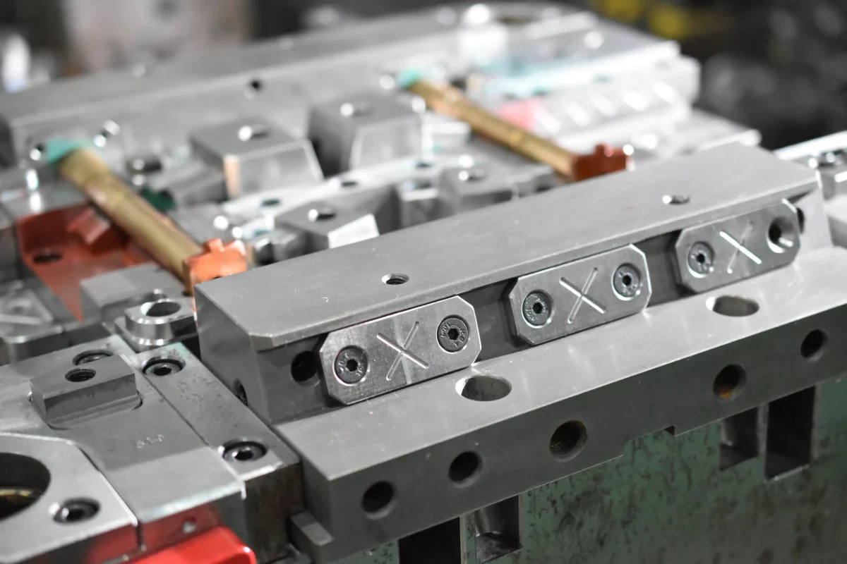
Complex plastic components can use side-action molds, lifters, collapsible cores, unscrewing systems, hot runners, insert molding, two-shot tooling, and conformal cooling. The right setup depends on undercuts, wall thickness, resin, tolerance, cavity count, and annual volume. A part with 1 mm walls, four side holes, and an internal thread may need several mechanisms in one mold. Hot runners can remove runner scrap that may equal 50%–250% of part weight, while well-designed cooling often has the largest effect on cycle time. Mold construction should therefore be based on measurable geometry, process stability, expected cycles, and maintenance access rather than tool complexity alone.
A complex component usually becomes difficult to mold when several geometric conditions occur together. A housing may have 0.8–1.2 mm walls around the outside, 2.5–3.0 mm bosses around screws, snap hooks perpendicular to the mold-opening direction, and an internal connector that cannot be pulled from a straight core. Each feature changes filling, cooling, shrinkage, or release behavior, so one standard core-and-cavity arrangement is often insufficient.
The first engineering check is the direction in which every molded surface must leave the tool. Features parallel to mold opening are relatively simple. A side hole, lateral clip, or recessed groove usually needs a slide that retracts before ejection; a mold with four-sided functional geometry can therefore contain 2, 4, or even more independently guided slides.
Slides are normally moved by angle pins, cams, hydraulic cylinders, or other mechanical systems. Short travel and predictable timing suit mechanical actuation, while hydraulic movement is useful when a side core requires a longer stroke or cannot follow the normal opening sequence.
Adding a slide solves an undercut, but it also adds a shutoff surface, guide system, wear area, cooling restriction, and another location where dimensional alignment must remain stable after hundreds of thousands of cycles.
Internal hooks create a different release problem because an external slide often cannot reach them. Angled lifters move with the ejector system and shift sideways as they travel forward, allowing internal snap features to clear the steel before the part leaves the core.
The geometry has to provide enough lateral movement without forcing the lifter into excessive side loading. Even a 1 mm undercut may require more than 1 mm of practical clearance once draft, shrinkage, manufacturing tolerance, and safe release distance are included, which is why lifter angles and available ejector stroke should be checked together rather than separately.
Cylindrical parts with internal grooves or deep circular undercuts can use collapsible cores. The core remains expanded during injection, then its segmented body contracts inward during release. Caps, connectors, medical fittings, fluid-management components, and valve parts are common examples.
Collapsible cores reduce the need to rotate a threaded core, but they need enough internal diameter for the segments and enough axial space for the mechanism. A 20 mm bore offers a very different design envelope from a 6 mm bore, so feasibility depends heavily on the actual dimensions rather than the presence of an undercut alone.
Internal threads bring another option: an unscrewing mold. Instead of pulling through the thread profile, the mold rotates the threaded core using gears, racks, hydraulic systems, or servo equipment. The part stays controlled while the core follows the thread pitch out of the plastic.
Unscrewing becomes more useful as the thread becomes deeper, stiffer, or less suitable for stripping. A component molded in a flexible polymer may tolerate limited thread stripping, while a glass-filled engineering resin with low deformation tolerance generally gives the mold designer much less freedom.
| Part feature | Common mold solution | Main engineering issue |
|---|---|---|
| External side hole | Slide / side core | Retraction distance and locking force |
| Internal snap hook | Angled lifter | Side load and release clearance |
| Circular internal undercut | Collapsible core | Core diameter and collapse space |
| Precision internal thread | Unscrewing core | Pitch, rotation and cycle time |
| Metal terminal or bushing | Insert molding | Position repeatability |
| Two colors or polymers | Two-shot mold | Material bonding and indexing |
| Large irregular hot area | Conformal cooling | Temperature uniformity |
Once release geometry is workable, melt delivery becomes the next concern. Long flow paths, thin walls, multiple ribs, and large projected areas can make one conventional gate inadequate. A hot-runner manifold places heated channels close to the cavities and can feed several gate locations without creating a cold runner after every shot.
Cold-runner material can equal 50% to 250% of molded part weight in some designs, according to Mold-Masters, and regrind allowance may be limited by material or application requirements. Medical production may require virgin material, making a large cold runner direct scrap rather than reusable feedstock.
Hot runners are not automatically better for every project. They require heaters, thermocouples, manifold seals, temperature control, and maintenance access. Heat-sensitive polymers also need controlled residence time because thermoplastics degrade when exposed to elevated temperature for too long.
Valve gating adds another level of control. A mechanical pin closes each gate after packing rather than waiting only for the gate to freeze. Valve gates can be sequenced across a long component, allowing the melt front to move from one area to another instead of filling every location at the same instant.
For a 700 mm automotive trim part, for example, several gate positions may reduce the flow distance compared with a single end gate. The actual gate count must still be verified with filling analysis because increasing the number from 1 to 4 does not guarantee better quality if the weld lines move into clips, sealing surfaces, or appearance areas.
Insert molding is useful when the plastic part must contain metal threads, electrical terminals, bushings, magnets, pins, or reinforcement. The insert is positioned before injection, and plastic forms around selected surfaces so a separate post-molding installation step can be removed.
Repeatability matters because a metal insert displaced by even 0.2–0.5 mm can reduce local wall thickness, alter terminal position, or contact cavity steel. Higher-volume cells therefore often combine mechanical locating features with robotic loading and presence sensing before the mold is allowed to close.
The same idea extends to overmolding, where a second polymer forms over a molded substrate. A rigid handle may receive a softer grip, while an enclosure can receive an integrated sealing region instead of using a separately assembled gasket.
Material pairing must be checked before the mold is finalized. Two polymers may process within similar temperature ranges yet provide poor adhesion, while large differences in shrinkage can bend the finished component after cooling. Mechanical interlocks are often added when chemical bonding alone cannot provide the required retention.
Two-shot molds automate that sequence inside one molding system. After the first shot, a rotating platen, index plate, or transfer mechanism moves the first component into another cavity position before the second material is injected.
A 2-material tool is more expensive and mechanically demanding than a conventional mold, but high annual volumes can justify removing manual transfer, fixture loading, and a separate molding operation. The production calculation should compare total parts per year, cycle time, labor content, scrap rate, and expected tool life rather than only the initial mold quotation.
Cooling deserves equal attention because injection molding cycles often spend more time removing heat than filling the cavity. Straight drilled water lines work well around simple cavities but cannot closely follow deep ribs, tall cores, curved housings, or tightly packed inserts.
Conformal cooling uses internal channels that follow the cavity surface more closely and is commonly produced with metal additive-manufacturing methods. The aim is to reduce temperature differences between sections; a hot boss cooling much slower than a 1 mm wall can create sink, local shrinkage, and distortion even when both regions fill correctly.
A faster cooling circuit is useful only when temperature remains controlled across the part. Cooling one region aggressively while another remains hot can shorten machine time yet worsen dimensional repeatability.
Complex molds also benefit from replaceable inserts around high-wear regions. Glass-fiber-filled polymers can abrade gates, runners, shutoffs, and cavity surfaces much faster than unfilled materials, so rebuilding a small insert is usually more practical than repairing an entire cavity block.
Maintenance access should therefore be designed while the tool is being engineered. A 500,000-cycle production program behaves differently from a 5,000-part prototype program; slide wear plates, lifters, seals, heaters, valve pins, ejectors, and sensors need different levels of serviceability at those volumes.
Cavity pressure and temperature sensing can also help when a complex part has narrow processing limits. Machine pressure shows what happens in the molding machine, while a cavity sensor measures conditions closer to the molded polymer, making it easier to compare filling and packing behavior from shot to shot.
The mold should not become more complicated than the product requires. Moving a snap hook 3 mm, changing its opening direction, adding draft, or relocating a side hole can sometimes remove a complete slide assembly. Early design-for-manufacturing review is therefore usually cheaper than solving every geometric issue through additional mold mechanisms.
A practical selection sequence can be kept short:
-
Map every feature against the mold-opening direction and mark all undercuts.
-
Record minimum and maximum wall thickness; compare 0.8 mm thin regions with 3–4 mm bosses or junctions.
-
Check resin shrinkage, fiber content, processing temperature, and stripping flexibility.
-
Estimate annual volume, cavity count, required cycle time, and expected lifetime cycles.
-
Select slides, lifters, collapsible cores, or unscrewing systems only where geometry requires them.
-
Review gate location, weld-line position, venting, pressure loss, and cooling before steel cutting.
-
Design access for components expected to wear or require routine replacement.
Production economics should then determine whether a cold runner, hot runner, manual insert system, robotic insert cell, or multi-shot mold makes sense. Some specialized hot-runner platforms are designed for cycle times below 2 seconds, while other technical components may run at 30–60 seconds because wall thickness and cooling dominate the process.
For companies comparing several tooling routes, Qlution Manufacturing can be evaluated in the same way as any technical mold supplier: review DFM capability, mold-flow support, tool-steel specification, hot-runner integration, dimensional inspection, trial documentation, spare-part planning, and experience with the intended resin and geometry.
Supplier evaluation should also include what happens after the first acceptable sample. A mold may pass an initial 100-part run but later show flash at slide shutoffs, inconsistent ejection, heater failure, or dimensional drift during long production runs, so validation conditions should resemble the planned manufacturing environment.
For a demanding component, mold trials are better treated as process verification than visual approval. Record fill time, peak pressure, melt and mold temperature, cooling time, part weight, dimensional measurements, and cavity-to-cavity differences; a 16-cavity tool needs data from all 16 cavities rather than one convenient sample.
A stable mold solution therefore comes from matching each physical feature with the least complicated mechanism that can release it repeatedly, then checking melt flow, heat removal, wear, automation, and service access around that architecture. A mold that makes one good sample is not enough; production tooling has to reproduce the same geometry across the planned cycle count and cavity population.